
Overview
In early 2023 I looked into the way that the radio is wired in on the Barchetta and found out a few things that might be more widely useful so they are recorded here. The information may be useful to anyone doing DIY work on their own Barchetta or to pass to an auto-electrician who may not be familiar with the car.
Much of the investigative work was performed on a thread on the Fiat Forum and I thank those involved in that discussion.
Caveats
Firstly, this information is the result of looking at precisely one car with some corroboration from other Fiat Forum members. It may be that later cars are wired differently but the wiring diagrams seem to stay consistent as far as I can tell.
Secondly, I’m not a qualified mechanic or electrician so I can’t guarantee that any approach outlined here is ‘correct’.
Background
When I inherited my Barchetta it came with an aftermarket Sony radio. I quickly became aware that unless I turned the radio off or removed the faceplate the car battery would drain flat in the time it took for the sun to shine again.
ISO 10487
ISO 10487 was created in 1995 to standardize the connections between head units and car wiring harnesses. Since the Barchetta is also of a similar vintage then that may be an explanation for an issue we discuss later.
You can read a good summary of the standard on Wikipedia but I’ll summarise the salient parts.
There are four connectors covered by the standard they are:
- Power
- Loudspeakers
- Miscellaneous
- Navigation
Only the first two concern us for the Barchetta and we’ll mostly be looking at the power connector.
The layouts of the power and speaker connectors are shown in the diagram below:
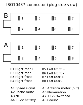
On the Barchetta only A4, A5, A6, A7 and A8 are connected.
The key thing to note is that there are three connections that can carry 12V:
- A4 – always live at 12V. Needed to keep any internal memory alive. Should be low current draw to avoid flattening the battery
- A6 – at 12V when the headlights (and ignition) are on. Useful to adjust the illumination of the radio at night.
- A7 – at 12V when the ignition is on. This should be for the large current draw items that are only needed when the radio is working
The Barchetta’s version
Now consider the Barchetta wiring diagram below:
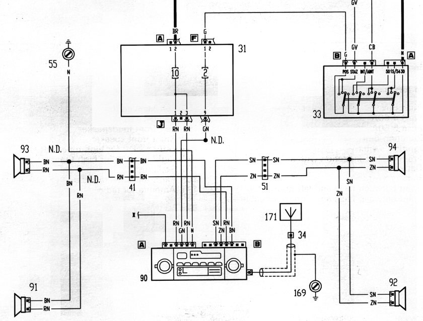
It can be seen that connector A to the radio (part 90 at the bottom) has five wires. Going from left to right and using a voltmeter to check what they do:
- A lead that goes to the aerial motor. Not labelled but, on inspection, is yellow.
- A lead that is labelled RN (Rosso/Nero or red and black). This lead is always at 12V.
- A lead that is labelled GN (Giallo/Nero or yellow and black), this is only at 12V when both the ignition and headlights are on. You can trace the lead back to component 33 which is the ignition switch.
- Another RN lead, also always at 12V.
- A lead that is labelled N (Nero or black) and goes to a -ve terminal somewhere.
It can be seen that connections 2 and 4 are joined together in the junction box labelled ’31’ on the diagram. These two connections, 2 and 4, should equate to A4 and A7 in the ISO standard connector but it looks like Fiat did not follow the standard and made them both +12V at all times. I believe that this is the reason that after market radios can drain the battery as they have no way of knowing when the ignition is off.
Creating a switched supply – one solution
I decided to fix this issue on my car and I’ll outline my solution here. There may be other ways of achieving the same goal but this was mine.
Firstly we need to find a wire that is at +12v only when the ignition is on. I couldn’t see any obvious candidates in the area until, by chance, there was a discussion about the clock. This led me to a page on the Barchetta lexicon website that discusses the clock wiring. The wires going to the clock are as follows:
- red-black = continuous plus
- black = ground
- orange = switched plus
- yellow-black = +12V when the headlights are on
The orange wire has what we need, a switched +12V lead. Using information on changing the clock bulb from this site I got to the clock wiring on my car and verified the information using a voltmeter. Now we could just splice into this orange wire and use it to supply connector A7 but since the wire is very thin it would not handle the current needs of the radio. For this reason I used a small switching relay (Bosch part number 0332019110) to allow the orange clock wire to switch the wire going to A7.
As a newcomer to auto electrics I found information on relays and their terminal numbers on the following pages very useful: